The right industrial vacuum system can significantly improve a facility’s energy efficiency – in some cases, reducing use by up to half
.jpg)
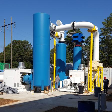
Assembling the turnkey vacuum system for the client’s required factory acceptance test (FAT) at the pdblowers facility required construction of a test pad, as well as rental of two one-megawatt generators and a step-up transformer to generate the required 4160 voltage.
A customer came to Georgia-based pdblowers seeking one of its designs for a west coast facility. The customer, the aerospace division of a large industrial manufacturer, uses a large altitude simulation chamber to test aircraft parts at different atmospheric conditions.
It was based on this application, said pdblowers President Jim Hene, that his team created what the facility needed: a multi-stage vacuum system that could manage varying mass flows at different vacuum levels.
“Variable speed vacuum systems can significantly enhance energy efficiency and operational flexibility,” Hene said. “Our work with this customer is a practical example in which we employed best practices from start to finish.”
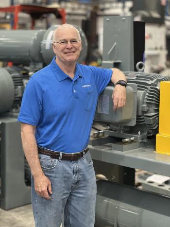
Jim Hene, president of pdblowers.
Zero Water Is an Essential Requirement
The aerospace project involved the replacement of a two-stage, water-injected system that had turned into a one-stage vacuum system after one stage went out of service. The existing system always operated at full flow and horsepower.
pdblowers needed to work within two specific constraints: the customer’s requirement for a dry system with no water, which was largely due to strict regulatory requirements, and its need for a turnkey solution that could be fully assembled at the manufacturer’s facility for a factory acceptance test (FAT).
The customer first took its scenario to Roots Blower, the largest manufacturer of positive displacement vacuum pumps and the inventor of rotary lobe blowers. Roots was acquired by Ingersoll Rand in 2023. A partner of pdblowers, Roots brought the opportunity to Hene as the on-site FAT was a hinderance to its own production – whereas pdblowers had the capacity and capability to accommodate the request.
The partnership between pdblowers and Roots is a long one; the companies share significant expertise in vacuum and pressure solutions. pdblowers has been a Roots agent since 1998 and is consistently its top distributor.
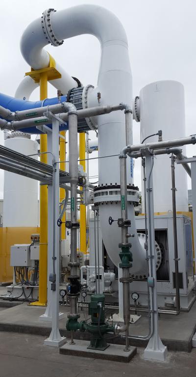
Installed at a large aerospace manufacturing facility, the multi-stage vacuum system is used in conjunction with an altitude simulation chamber to test aircraft parts at different atmospheric conditions.
A Large System With Large Requirements
With a requirement that the system could specify mass flow and vacuum levels at multiple points, pdblowers went to work, noting that it also needed to handle flows of over 20,000 cfm and vacuum levels greater than 2 psia (.14 bar).
Since the upgrade would be a dry system, no water could be introduced into the process air. “High vacuum systems typically use water-injection to cool the equipment allowing it to reach the necessary vacuum levels,” Hene said. “The old system being replaced was a water-injection system. Having water in the system leads to many regulatory requirements around the handling of the wastewater. A primary goal of this project was to implement a dry system with no water to reduce the environmental impact and its associated regulatory burden.”
The new system would certainly be large, and with a large power requirement, pdblowers noted that the culmination of the project, the FAT, could be quite burdensome to achieve.
The solution, said Hene, was a two-stage configuration, specifically a two-stage positive displacement vacuum system with independently controlled stages. The first stage would have a higher mass flow at its core along with a lower vacuum level, while the second stage would run opposite with lower mass flow and higher vacuum level.
“We designed the system so both stages could run simultaneously, or each stage could be used alone if the client only needed the mass flow or vacuum capabilities of that particular stage, leading to significant energy savings,” Hene said. “For instance, if the client needs a higher mass flow but not as much vacuum, the first stage will run independently, using valves and piping to bypass the second stage.”
pdblowers also implemented variable speed drives (VSDs) into its design to realize the variable speed needed. Use of a variable frequency drive (VFD) is key to real-time adjustments of vacuum levels. The customer control system, meanwhile, provides an operator the ability to input mass flow and vacuum level. With the information entered, the system can convert those metrics to speed and volumetric flow, then identify whether one or both stages are needed to achieve a result.
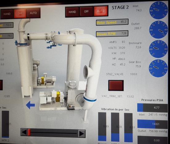
Behind the scenes, the VFD control system performs complex calculations to determine each machine's speed and compression ratio, while the operator is presented with a simple user-friendly HMI to input conditions and monitor the system.
Selecting the Right Blowers for the Job
As pdblowers entered the planning phase for the customer’s project, it first wanted to determine the vacuum pump (or blower) combination needed to hit the required, and varied, mass flows and vacuum levels. The first crucial factors to this were minimum allowable operating speeds and maximum allowable temperature rise.
“In general, blowers are more or less limited to a 2:1 compression ratio, unless you have a unit specifically designed for dry vacuum,” Hene said. “A Roots dry vacuum jetted [DVJ] unit can hit a higher compression ratio. As the vacuum level goes up, there is a port that pulls in atmospheric air into a pre-discharge chamber. That atmospheric air mixes in and cools the unit down, allowing it to operate at higher vacuum levels without exceeding the maximum allowable temperature rise.
“This comes at a cost of efficiency; this is where we pay the price for not having water in the system,” he added.
To meet the customer’s target conditions, pdblowers selected two Roots rotary lobe blowers. It chose a Roots gas blower for the first stage that could provide 20,000-plus cfm at a vacuum level up to 16-in Hg(g). For the second stage, the company selected a Roots DVJ blower supported by an intercooler that could provide 12,000 cfm at up to 24-in Hg(g).
The support equipment pdblowers selected included VSDs and motors. For the former, pdblowers made its choice because the characteristics of positive displacement blowers required a constant torque VSD capability.
“Variable torque is applicable to centrifugal blowers and fans where constant torque is applicable to positive displacement equipment,” Hene said. “When the torque requirement is the same regardless of speed and power, you may have to consider a larger VSD to maintain your safety factor.”
Additionally, he noted, any VSD system must be cognizant of restrictions on the minimum allowable speed of the blower and motor and temperature rise. As speed at constant vacuum levels are decreased, the temperature will go up, so pdblowers wanted to ensure the VSDs were adequately sized.
When examining the motors element of the system, it selected two 800-horsepower (hp) units for the customer’s target performance, one for each stage.
“Both blowers would be operating at or below 1,000 rpm and after completing our torque calculations, we determined that rather than using expensive low rpm motors, we would be able to use more cost-efficient 1,800 rpm motors and limit their rpm to the desired output with a parallel shaft gearbox,” Hene said. “In this case, since the gear for the blower was larger than the gear for the motor, it gave us adequate torque.” He added that the client’s power requirement was 4,160 volts, as the amperage is lower when the voltage is higher; thus, it selected 4,160v for the motors and VFDs.
Next on pdblowers’ task sheet was the control system. It sought to coordinate the two machines so they would always be in step with the limits on each machine.
“Thanks to the constant flow provided by a positive displacement blower, it’s possible to use the blower as a meter. Through our software, we used the speed of the blower and various operating conditions (inlet vac, temp, etc.), to calculate the volumetric throughput (+/-5%),” he said.
The system is designed to calculate the speed needed and compression ratio for each machine to operate optimally, then adjust as needed. For example, when more mass flow is needed, the first stage maintains the same compression ratio while the second stage makes minor speed changes to increase its compression ratio to meet the overall vacuum need.
“Our custom control system would feature an operator-friendly Human Machine Interface [HMI] to easily input the required mass flow and vacuum level, and monitor how the system is performing,” Hene said of the control’s capabilities. “The client’s long-term plans include tying our control system into their existing test software.”
Finally, the needed structural components in the design were considered, and pdblowers noted there were many puzzle pieces in that the system needed many structural components to support the vacuum pumps, silencers and other equipment.
It subsequently retained a pair of structural engineering firms, one to design the foundation and the other to create the piping design. Both selected firms were local to the customer’s facility and also skilled in both the regulatory and geological variances of the region. All of the structural elements were custom fabricated by pdblowers.
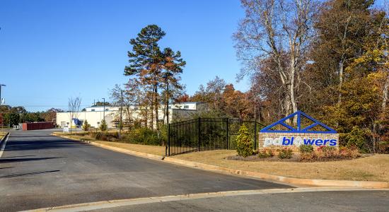
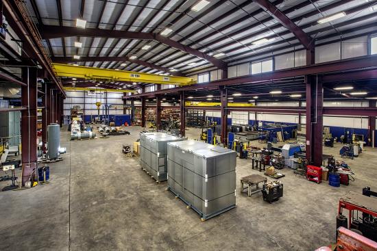
The 50,000-square-foot facility at pdblowers’ campus in Gainesville, Georgia.
Demonstrating the System With a FAT
As a factory acceptance test, or FAT, was a major requirement for the client, the demonstration was planned at pdblowers’ campus in Gainesville, Georgia.
“The system was so large it could not be assembled inside our 50,000-square-foot facility,” Hene said, noting that a new 12-inch-thick concrete pad needed to be poured and outdoor electrical panels added to properly support the system. pdblowers also rented two one-megawatt generators and a step-up transformer to take the generators’ output from 480 to 4,160 volt. Finally, the VFDs, control panels and all other electrical gear were mounted in a 40-foot container – a makeshift mobile command center for the FAT – that was shipped directly to the final installation site after the demonstration was complete.
“A client representative was on-site for a demonstration of the system’s operation, fully functional at all flow points and vacuum levels,” Hene said. With the FAT complete, the entire project was ready to make the trip to its final destination.
VSDs for Flexibility
Eight individual trucks were loaded to get the entire system where it would be installed, and a customer-appointed contractor met Hene’s team in California to help assemble it. A pdblowers engineer arrived post-install to assist with the system’s start-up.
Looking at the lessons learned from this project, Hene urged the use of variable speed systems to others in similar situations. Experts like pdblowers can tailor a solution and make the entire project easier and more fluid. “By providing a dry multi-stage system controlled by VSDs, the client immediately realized much more flexibility in their testing, sizable energy savings by using only the exact amount of energy needed and cost savings by removing all regulatory burdens of wastewater treatment,” he added.
Blower Best Practices
|
Images courtesy of pdblowers.
About pdblowers
pdblowers specializes in blower and vacuum pump technologies. From system integration to ground-up fabrication, it provides blower and vacuum pump solutions across a wide range of industries. At its 50,000-square-foot production facility and headquarters in Gainesville, Georgia, it builds specialty equipment enclosures, positive displacement blower packages, multi-stage vacuum systems, soil remediation equipment, certified UL control panels and more. For more information, visit https://www.pdblowers.com.
For similar articles on Industrial Vacuum Technology, visit https://www.blowervacuumbestpractices.com/technology/medium-high-vac.
Visit our Webinar Archives to listen to expert presentations on Industrial Vacuum Technology at https://www.blowervacuumbestpractices.com/magazine/webinars.