The ideal blower control matches the blower airflow to the process demand. The process demand, in turn, must be established by the aeration control system.
Historically, aeration control systems have been feedback control with basin dissolved oxygen (DO) concentration as the controlled process variable. This control strategy has become standard practice in most treatment facilities because of its proven effectiveness in reducing energy consumption and improving process stability.
Increases in process complexity and demands for greater sustainability have driven innovation in control system strategies. Meeting these demands has resulted in the implementation of new strategies, more capable controllers and new sensor technologies. These developments all influence blower control. In many cases, owner requirements include incorporating advanced aeration controls into the blower system itself.
Process Basics
Activated sludge with diffused aeration is the dominant technology in wastewater treatment. This is a biological process, with microbes suspended in the mixed liquor requiring oxygen to metabolize organic wastes and convert ammonia (NH3) to nitrate (NO3). Efficiently controlling the airflow rate and oxygen supply to the process is the key to optimizing both energy consumption and process performance.
The advanced control systems discussed in this article do not replace DO control systems. Instead, they enhance the accuracy of determining the process demand for air or optimize the blower’s performance.
Floating Control
The most common control algorithm used for process control is Proportional-Integral-Derivative (PID). Although PID is effective for many process control strategies it has limitations that affect its application to aeration control and DO control. The PID algorithm can be difficult to tune and is prone to hunting. PID control accuracy is impaired by long process response times and non-linear process response, both characteristics of the aeration process. A response to these shortcomings is floating control, sometimes referred to as “adjust, wait and see.”
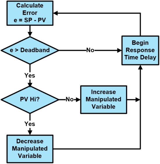
Floating control logic.
Floating control tuning is more intuitive than tuning PID algorithms. The response time delay can be set to accommodate process response. The increase and decrease of the manipulated variable can be fixed steps or proportional to the error. It’s common to have different values for increase and decrease to reduce hunting.
Most-Open-Valve (MOV)
MOV logic is intended to minimize the blower discharge pressure by keeping the aeration zone control valves as open as possible while maintaining set flow rates. This minimizes the restriction to flow, which optimizes system pressure and blower power draw.
There are two principal MOV systems. The first works by manipulating the pressure’s setpoint. The second manipulates valve positions and air flow directly.
Traditional blower controls work to maintain a constant discharge pressure. The blower control logic and aeration basin control logic operate independently. When valves at individual aeration control zones open or close to meet higher or lower process demand, the system backpressure decreases or increases. This causes the blower control to increase or decrease airflow to match the new system demand, which increases or decreases system pressure.
In most instances where the MOV refinement is added to pressure control the position of the zone valves is monitored by a master control panel. If one of the zone valves closes below a set maximum position, for example 60%, the pressure setpoint incrementally decreases. This causes the blower output to decrease, which in turn results in lower flow to the aeration zones. The valves open to meet airflow demand. After a few iterations, the system stabilizes with the required flow provided to the process at a lower pressure, saving energy.
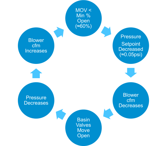
Pressure-based MOV logic.
If the position of the valve that is most open is above a set maximum position, for example 70%, the above logic is reversed.
Pressure-based control works well if the blowers have adequate turndown. However, if the blower system is operating at the minimum allowable flow rate, all of the basin valves tend to travel towards the minimum open position. This reduces the air flow, raising the discharge pressure. If the blowers are at the maximum available flow all of the basin valves open, attempting to get more air. In both circumstances flow control accuracy is lost.
MOV with Direct Flow Control
An alternative to pressure-based control is modulating system air flow rates based directly on airflow demand at the basins. This method generally provides more stability than pressure-based control. It relies on the ability of the master control panel to monitor and control both the blower’s local control panels and the aeration basins.
Two techniques are implemented in the direct flow control method:
- The valve at maximum position – the most open valve – is not allowed to close until another valve reaches maximum position. The max position for a butterfly valve is typically set at 60% to 70% open.
- The target air flow used by the aeration zone flow control loop is based on a proportion of the total process demand and not on the process demand calculated by the DO control logic. This ensures if one zone is above its target flow, another will be below its target flow. In direct flow control there are three air flow rates associated with each control zone: the actual measured air flow rate, the process demand air flow rate based on DO control logic and the setpoint for the air flow control logic used to manipulate the valve. This is apportioned from the actual total flow rate and the total process demand from all zones.
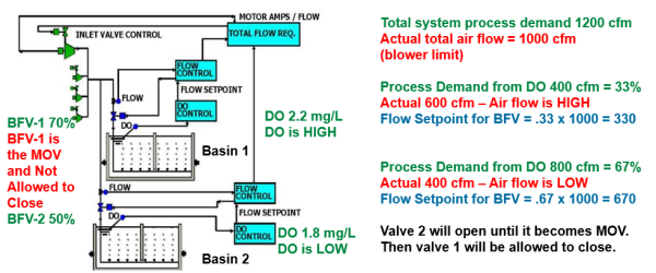
The logic is best understood by a simplified example: The initial system status is shown in the accompanying diagram. The total actual air flow from the blower system is less than the total process demand, meaning the blowers are maxed out. The maximum allowable valve travel is 70% open. The DO in basin 1 is above setpoint, and the DO logic will want to decrease the air flow. However, it is the most open valve, so the logic inhibits closing the control valve. Basin 2 DO is low, and its process demand is increasing.
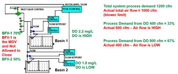
Example of MOV with direct flow control.
The total process demand, based on DO control loops, is 1,200 cfm: 400 for basin 1 and 800 for basin 2. Basin 1 will base its flow control setpoint on the apportioned fraction of the total process demand and the total actual air flow:
(400 cfm)/(1200 cfm)=0.33 and 1000 cfm x 0.33=330 cfm
The flow control setpoint is calculated for basin 2 in a similar manner:
(800 cfm)/(1200 cfm)=0.67 and 1000 cfm x 0.67=670 cfm
Note there are two ways to decrease the air flow to basin 1: close the valve controlling its air flow, or open the other basin’s control valve, diverting air from basin 1 to basin 2.
After the apportioning is calculated, the air flow setpoints are implemented by the individual basin’s flow control loops. Because it is the MOV, the basin 1 valve doesn’t close, but the basin 2 valve will open. If basin 2 reaches its apportioned setpoint before reaching 70% open it will cease travel. If the basin 2 valve reaches 70% open, it will become the MOV and the basin 1 valve will begin to close. As the basin 1 valve closes, it will decrease its air flow and divert air to basin 2. When both basins reach their set airflow, valve movement will cease.
Both basins have reached their set airflow.
Ammonia-Based Aeration Control (ABAC)
The oxygen demand for converting ammonia to nitrate often doubles the total airflow requirement. The amount of oxygen required is determined by the stoichiometric ratio, 4.6 pounds of oxygen to each pound of ammonia converted. The airflow required is influenced by the oxygen transfer efficiency (OTE) of the aeration system. Because OTE improves at lower DO concentrations there are energy savings available by maintaining the minimum DO concentration that meets process objectives.
ABAC systems take advantage of the influence of DO on both OTE and the rate of biological conversion of ammonia. Within upper and lower limits, the rate of biological conversion increases with increasing DO. There are many variations, but most ABAC systems operate by manipulating the DO setpoint in response to an ammonia measurement near the effluent end of the aeration basin. If the ammonia level rises, indicating the rate of conversion is inadequate, the DO setpoint is increased. When the ammonia concentration drops again, the DO setpoint is reduced.
Feedforward Aeration Control
Feedback control operates by responding to the difference between actual and desired process parameters. Feedforward control operates by directly responding to process load changes. This can minimize process errors and improve system stability.
Two things are necessary for feedforward control. First is the ability to measure the process load in real time – the oxygen demand of the aeration system. Second is a mathematical model of the process response to the controlled variable – the transfer of oxygen from the supplied airflow.
The required parameters are obtained from offgas analysis (below). By capturing the bubbles from the surface of the aeration basin and analyzing the residual oxygen content, the OTE can be calculated. The OTE and the measured airflow can provide the actual oxygen transfer rate (OTR) and oxygen uptake rate (OUR). The mathematical model of oxygen transfer uses the OTE to calculate the airflow necessary to sustain the DO concentration essential for maintaining the proper mixed liquor biology.
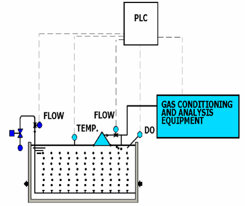
Offgas measurement system.
Summary
Fifty years ago, automatic air flow control based on feedback from DO setpoints was cutting edge technology. Since then, increasing process demands and increases in energy awareness have driven the development of new and more elaborate technologies. The descriptions provided above are far from comprehensive. They cannot cover the numerous variations employed and in development. Exploration of the literature and suppliers’ offerings is necessary to determine whether or not an advanced process and blower control strategy is appropriate for each application.
About the Author
Tom Jenkins has over 40 years’ experience in blowers and blower applications. As an inventor and entrepreneur, he has pioneered many innovations in aeration and blower control. He is an Adjunct Professor at the University of Wisconsin, Madison. Tom is the current Chair of the ASME PTC 13 Committee. For more information, visit https://www.jentechinc.com.
For similar articles on Aeration Blower System Assessments, please visit https://www.blowervacuumbestpractices.com/system-assessments/blower-systems.
Visit our Webinar Archives to listen to expert presentations on Aeration Blower Technology at https://www.blowervacuumbestpractices.com/magazine/webinars.